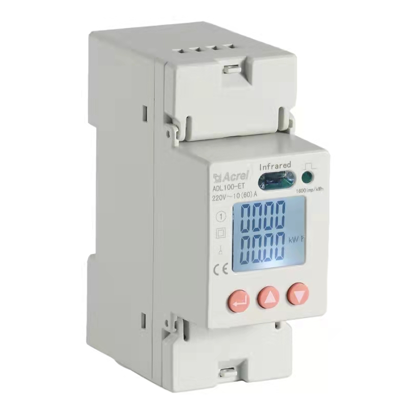
Energy Meters
Current Transformers
Power Monitoring And Controlling
Electrical Safety
Smart Gateways
Energy Meter Application
Solar PV Meter for Photovoltaic System Solutions
EV Meter for Charging Pile Energy Management System Solution
Wireless Temperature Monitoring System
Energy Meter Hardware for Telecom Tower RMS Solution
Precision Distribution Monitoring Solution for IDC
ABAT100 Series Online Battery Monitoring Solution
Medical Isolation Power Supply Device
Energy Meter for IOT Cloud Platform
Arc flash protection solutions
Smart Motor Control and Protection Solution
Residual Current Operated Relay
Prepayment Cloud Platform
Smart Busway Monitoring Solution
Acrel-2000ES Energy Storage Energy Management System(EMS)
Acrel-2000MG Microgrid Energy Management System
AcrelEMS-IDC Data Center Comprehensive Energy Efficiency Management Solution - Case Study of a Project in Inner Mongolia of China Mobile
AcrelEMS-IDC Data Center Comprehensive Energy Efficiency Management Solution - Case Study of a Project in Inner Mongolia of China Mobile
Misconceptions in the Use of Current Transformers and Precautions in Work
Power transformation and distribution monitoring solution for user substations
Acrel Energy Monitoring Solution for Building
Global Chain Store LAWSON Online EMS Project
ATE800 Series RFID Wireless Temperature Measurement Sensors
CE Certification Standard EN 61010 Test Requirements
480V Din Rail Mounted 50ms Response Rate Three-phase Unbalanced Anti-reverse Current Multi-function Energy Meter
Acrel ADF400L-2H-CE Din-rail Ethernet Interface Electricity Meter
Wireless Temperature Monitoring in the Philippines
Acrel DC Energy Meter for EV Charging Stations
Telecom Tower Power Monitoring Projects
MV/LV Transformer Monitoring
Demand Requirement in Electricity Consumption
New Options for Balcony Solar Power Systems
LoRaWAN Energy Internet of Things Solutions
Hospital Electrical Safety Products and Solutions
Main functions of data center computer room
The Use and Principle of Current Transformer
Acrel Support Olympic Winter Games Beijing 2022
Power Supply Solution for Winter Olympics
Wireless Temperature Solution at Beijing Daxing International Airport
Acrel Releases ADW300 with 333mV Access
Energy meters used in urban comprehensive pipe gallery projects
Base Station Energy Consumption Monitoring Solution
Application of Residual Current Monitor in Street Lighting
Discussion on the Combination of MQTT
Comprehensive Insights into Temperature Measurement in Industrial Processes
DIN Rail Energy Meters: A Comprehensive Guide
Operational Principles of Medium Voltage Protection Relays
Working Principles and Wiring of Various Types of Electric Meters
Digital Electric Energy Meter VS Electronic Electric Energy Meter
Problems and Common Fault Analysis of Current Transformers During Operation
Detection and Marking of Current Transformers
The Functions and Working Principles of Current Transformers
Application of DC Current Meters in Substation DC Measurement
Operation Methods and Precautions of Current Transformers
The Detection and the Open Circuit Fault Inspection of Current Transformers
Models, Structures and Installation Methods of Different Hall Current Sensors
The Working Principles of the DC Current Shunts
How to Set the Temp and Humidity Controller?
Precautions of Multifunction Meter Storage
Principle and Characteristic Parameters of Hall Current Sensor
Multi-function Instrument Definition and Troubleshooting
The Use of Prepayment Energy Meter and Its Advantages over Induction Meter
Basic Functions of Smart Prepaid Electricity Meter in Student Dormitories
How to Use the Multi Function Energy Meter? What Functions Does It Have?
Factors That Affect the Performance and Use Value of Prepayment Energy Meter
Application of IoT Based Electricity Energy Meter
Application of Wireless Temperature Sensor in Press
What is the Significance of Smart Energy Meter Applications?
Smart Energy Meter Application
What Are the Common Faults of Current Transformers?
Operation Precautions of Current Transformers and the Cause of Burning
The Principle and Use of Through-core Current Transformers
The Wiring Principle of Current Transformers
Design Features of Wireless Temperature Sensors
Errors of Daily Current Transformers
Common Problems and Solutions of Multifunctional Power Meters
A Brief Introduction to the Application and Specifications of DC Shunts
What Do You Need to Know to Apply DC Shunts?
What Are DC Shunts Made Of?
Precision DC Shunts Are High Precision Resistors That Are Critical to Precision Requirements and Accuracy
Application Analysis of Current Transformers
Fixing Method of Split Current Transformer
What is a Smart Gateway?
The Difference Between Current Transformer and Zero Sequence Current Transformer
Can Ordinary Current Transformers Be Used As Zero-sequence Current Transformers?
Structural Difference Between Through-core Current Transformer and Ordinary Current Transformer
Wiring Principle of Through-core Current Transformer
Introduction to the Principles of Use of Open Current Transformers
The application scope of zero sequence current transformer is introduced
Standard for operation of three-phase integrated current transformers
Installation and use of current transformer
How to choose the core type of open current transformer?
Working Principle, Structure, and Method for Determining Saturation Point of Current Transformer
Confirmation of Current Transformer Saturation Level and Accurate Measurement of Saturation Points
Inspection of Connection of Current Transformers
Causes and Preventive Measures of Burnout in Current Transformers
What Is the Reason for Burnout of Current Transformers During Use?
Differentiation of Types of Current Transformers
Installation Requirements and Fixing Methods of Split Core Current Transformers
Considerations for Operating Current Transformers
Issues and Solutions for Installation of Zero-Sequence Current Transformers
What Are the Issues to Be Aware of During the Operation of Open-Type Leakage Current Transformers?
Application and Requirements of Zero Sequence Current Transformers
Principles, Functions, and Classification of Zero-Sequence Current Transformers
Main Technical Requirements for Current Transformers
Fault Detection and Handling Methods for Open-circuit and Short-circuit on the Secondary Side of Current Transformers
Teaching You the Correct Use of a Through-core CT Current Transformer
Operation Considerations and Installation Methods of Split-core Zero-sequence Current Transformers
What Do These Parameters Represent in the Din Energy Meter?
Main Performance of Open-Type Current Transformers
Selection and Calculation of Actual Usage of the Din Energy Meter
Things You Don't Know About the Din Energy Meter
What Functions Does the Multi-functional Smart Din Rail Electricity Meter Have?
Breaking Barriers: How Wireless Technology Transforms Temperature Monitoring in Industry
From Factory Floors to Warehouses: Industrial Applications of Wireless Temperature Monitoring Systems
Smart Solutions for Energy Monitoring: Harnessing DC Digital Multifunction Meters
Smart Energy Monitoring Made Simple: The Magic of Multi-Function Energy Meters
Understanding DC Digital Multifunction Meters: Features and Applications
Demystifying DIN Rail Meters: A Comprehensive Guide to Their Functionality
From Voltage to Current: The Versatility of DC Digital Multifunction Meters
Din Rail Meters: Unlocking Precise Energy Measurement in Your Electrical System
Choosing the Right Din Rail Meter for Your Specific Energy Monitoring Needs
Cutting the Cords: Advantages of Industrial Wireless Temperature Monitoring Systems
Saving Energy, Saving Costs: How DIN Rail kWh Meters Make a Difference
Streamlining Energy Monitoring: Advantages of DIN Rail Mounted Electricity Meters
Efficient Energy Monitoring: Unleashing the Power of DIN Rail kWh Meters
Maximizing Space and Functionality: The Benefits of DIN Rail Mounted Meters
Unlocking the Potential: Applications of DIN Rail Mounted Electricity Meters
A Closer Look at DIN Rail kWh Meters: Features and Applications
Efficiency Redefined: How Multi-Function Energy Meters Are Transforming Energy Management
Unlocking Energy Insights: The Advantages of Multi-Function Energy Meters
From Factory to Field: Industrial Wireless Temperature Monitoring Solutions
Precision in Production: The Role of Industrial Wireless Temperature Monitoring
Behind the Scenes: How Hospital Isolated Power Systems Keep Healthcare Facilities Running
Powering Patient Care: the Importance of Hospital Isolated Power Systems
Measuring the Flow: The Science behind DC Current Meter Shunts
Powering Your World: How to Select the Ideal Power Meter Supplier
Efficiency in a Compact Package: The Benefits of Din Rail Electric Meters
Empowering Efficiency: The Role of a Power Monitoring Device
Overview of the importance of temperature monitoring in various industries
How Does a Multi-Function Energy Meter Compare to Traditional Energy Meters?
Do you Know a DC kWh Power Meter?
Your Essential Guide on How to Use DC Current Meter Shunts
The Role of Isolated Power Panels for Healthcare Facilities
Unveiling the Significance of DIN Rail Electricity Meters
Unveiling the Soaring Popularity of DIN Rail Electricity Meters
How to Choose the Right Multi-function Meter for Your Needs?
Din Rail Electricity Meter: Smart Choices for Efficient Energy Management
Types of Prepaid Meters: Navigating Efficiency in Commercial Power Management
Unveiling the Contrasts between Credit and Prepayment Energy Meters
Single Phase vs Three Phase Digital Energy Meters: Powering Industrial Efficiency
How Do I Install a DIN Rail Energy Meter?
How Can a 3 Phase Digital Energy Meter Help Identify and Detect Power Imbalances?
Dc Kwh Meter Provides Kwh-Based Charging for Dc Wallboxes
The Future of Isolated Power Panels in Hospitals
Electronics Essentials: Understanding DC Power Meter Circuitry Basics
Electrifying Vehicles: DC Power Meter Circuits in Electric Cars
Industrial Automation: Optimizing Processes with DC Power Meter Circuitry
Digital Dynamo: Harnessing the Latest Technologies from Your Power Meter Supplier
The Pulse of Efficiency: How to Evaluate an Energy Meter Supplier
Wirelessly Wise: Navigating the Benefits of IoT Energy Metering
Enhancing Medical Equipment Efficiency: The Role of DC Power Meter Circuits
Smart Monitoring, Smarter Savings: The Rise of IoT Energy Meters
Data-Driven Decisions: The Role of IoT Energy Meters in Sustainable Practices
Innovating Efficiency: How IoT Energy Meters are Revolutionizing Power Management
Safe Signals: The Importance of Cell Tower Radiation Meters in Telecom
On the Pulse: How Cell Tower Radiation Meters Safeguard Public Health
Educational Spaces and Signals: Deploying Cell Tower Radiation Meters in Schools
Ensuring Transportation Safety: The Significance of Cell Tower Radiation Meters Along Highways and Railways
Enhancing Safety and Wellness in Sports Arenas with Cell Tower Radiation Meters
Optimizing Healthcare Facilities: 3 Phase Digital Energy Meters in Hospitals
Empowering Industries: 3 Phase Digital Energy Meters in Manufacturing Plants
Sustainable Farming: The Role of 3 Phase Digital Energy Meters in Agriculture
Powering Smart Cities: 3 Phase Digital Energy Meters in Urban Infrastructure
Navigating Maritime: 3 Phase Digital Energy Meters on Seafaring Vessels
Navigating Complexity: How Digital Multifunction Meters Simplify Measurement
Beyond the Basics: Exploring the Capabilities of Digital Multifunction Meters
Smart Solutions for Smart Buildings: Digital Multifunction Meters in Commercial Spaces
On the Road to Efficiency: Digital Multifunction Meters in Automotive Manufacturing
Connected Campuses: Digital Multifunction Meters in Educational Institutions
How DC Energy Meters Enhance Solar Panel Efficiency in Any Climate
Mastering The Installation And Set-Up Of Digital Multi-Function Meters
The Role of DC Energy Meters in Monitoring Solar Panel Performance
Exploring the Versatility of Digital Multi-Function Meters in Industrial Settings
Unleashing the Power of Digital Multi-Function Meters
How DC Energy Meter for Solar Panels Contributes to Green Energy Practices.
The Role of Cell Tower Radiation Meters in Telecommunications
Exploring the Technology inside Cell Tower Radiation Meters
Integration of Renewable Energy Sources and IoT-Based Energy Metering
The Vital Role of Medical Isolated Power Panels in Infection Control Measures
Safety Features and Regulations for Medical Isolated Power Panels
Future Trends and Evolution of IoT-Based Energy Metering Technology
Din Rail kWh Meters in Industrial Power Management
Enhancing Patient Safety With Medical Isolated Power Panels in Healthcare Settings
The Role of DIN Rail kWh Meters in Business Energy Optimization
Din Rail kWh Meters for Accurate Data in Manufacturing Plants
Testing and Commissioning Procedures for Medium Voltage Motor Protection Relays
Key Features of Modern Medium Voltage Motor Protection Relays
Din Rail kWh Meters in Monitoring Power Usage in Schools
Enhancing Manufacturing Efficiency With DC Power Consumption Meters
Navigating Energy Efficiency With DC Power Consumption Meters
DC Power Consumption Meters in Optimizing Portable Device Usage
Advancements in Medium Voltage Motor Protection Relay Technology
Factors Influencing the Accuracy and Performance of Multi-Core Current Transformers
Dc Current Shunts and Their Crucial Role in Overcurrent Protection Systems
The Principles and Working of DC Current Shunts
Unveiling the Latest Breakthroughs in Multi-Core Current Transformer Technology
Factors Affecting the Accuracy of DC Current Shunts
Unveiling the Power of Multi-Core Current Transformers in Industrial Applications
Troubleshooting and Maintenance Tips for Multi-Circuit Power Meters
Installation and Wiring Considerations for Multi-Circuit Power Meters
Exploring Remote Temperature Measuring Devices in Healthcare
Multi-circuit Power Meters and Their Role in Utility Substations
How to Accurately Read and Interpret Data from a Single Phase DIN Rail Energy Meter
The Future of Single Phase DIN Rail Energy Meters
Exploring the Versatility of Single-Phase DIN Rail Meters in Commercial Spaces
The Importance of PV Meters in Optimizing Solar Energy Production
Remote Temperature Measuring Devices in Industrial Electrical Equipment
Revolutionizing Renewable Energy Usage with PV Meters
Advantages of Net Metering Using a PV Meter
The Role of Split-Type CTs in Advanced Metering Infrastructure
The Advantages of Split-type CTs in Space-constrained Environments
Application of Remote Temperature Measuring Device in Commercial Buildings
Installation and Setup of DC Power Monitoring Systems
Importance of DC Power Monitoring in Industrial Applications
Unveiling the Working Principle of Split-type CT
Unveiling the Hidden Potential Within Modern Power Systems
Latest Advancements and Trends in Split-Type CT Technology
Navigating DC Power Monitors for Commercial Buildings
Accuracy and Reliability of Open Current Transformers in Measurements
Multi-Data Meters in Industrial Process Monitoring
Multi-Data Meters in IoT and Connectivity Solutions
How Multi-Data Meters Transform Energy Management
Role of Open Current Transformers in Industrial Automation and Monitoring
Advantages of Using Open Current Transformers in Power Systems
The Function of Induction Meter in Campus
Revolutionizing Commercial Energy Management with IoT-Based Energy Meters
Real-time Energy Usage Tracking and Analysis with IoT Based Energy Meter
IoT-Based Energy Meters in Industrial Applications
How Smart Prepaid Electricity Meters Work
Benefits of Using Smart Motor Protection Relays in Industrial Applications
The Function of Smart Motor Protection Relay in Campus
Hospital Isolated Power: Ensuring Safety and Reliability in Healthcare Settings
How Smart Motor Protection Relays Help Prevent Motor Failures and Downtime
The Vital Role of Hospital Isolated Power in Medical Facilities
Benefits of Installing Smart Prepaid Electricity Meters
Role of Hospital Isolated Power Systems in Reducing Electrical Hazards in Healthcare Settings
The Role of Smart Prepaid Electricity Meters in Commercial Spaces
The Application of Smart Prepaid Electricity Meter in Campus
HANNOVER MESSE
Basic Principles and Functions of Medical Isolated Power Panels
Characteristics of Hospital Isolated Power Supply Systems
The Technology for Improving the Reliability of Medical Isolation Transformers
Applications of Multi-data Meters in Smart Grids
Necessity and Benefits of Telecom Tower Monitoring Systems
How Digital Multi-function Meters Work
The Benefits of Multi-function Electric Meters in Industrial Applications
Application of Wireless Smart Energy Meters in Energy Management
Application of Acrel infrared temperature measurement solution on dense bus duct of a lithium battery plant project
【Solution】Base station photovoltaic DC stacking energy efficiency management solution
How to Use Intelligent Motor Protection Relays to Improve Industrial Safety Standards
The Role of Multi-function Electric Meters in the Coordination of Smart Grids and Communication Networks
The Application and Exploration of Intelligent Motor Protector Relays in the Metallurgical Field
The Importance and Application of Hospital Isolated Power Systems in Hospital Buildings
Challenges of Safety and Efficiency in Operating Room Electrical Systems
Energy Monitoring and Analysis of Data Centers: Cutting-Edge Technology of 3 Phase Electronic Energy Meters
Energy Data Visualization and Intelligent Analysis for Telecom Towers
The Critical Role of Digital DC Power Meters in Solar Photovoltaic System Energy Management
Advantages of Industrial Intelligent Gateway
Usage Scenarios of Multi-Rate Multi-Function Energy Meter
Medical Isolated Power Supply Systems in MICU Wards
What Are Hospital Isolated Power Systems?
Advantages of Multi-Rate 3-Phase Digital Energy Meter
Energy Saving and Digital Management: 5G Telecom Tower Energy Management Solution
Data Center Three-Phase Smart Meter Energy Management
Advantages of Using Smart Prepaid Meters
Types and Applications of Current Transformer
Functions of Single-Phase DIN Rail Energy Meter
Leakage Current in Power Distribution System of Subway Stations
Applications of DIN Rail Energy Meters
Prepayment Energy Meters: A New Choice for Modern Energy Management
Difference Between Prepayment Energy Meters and Regular Energy Meters
DC Multifunction Meter: An Important Tool for Power System Monitoring
Role of Acrel Smart Meters in Monitoring and Analyzing Data Centers
Application of Hospital Isolated Power Systems
DC Meter's Application and Design in Iron Tower Base Station
Working Principle and Characteristics of Current Transformers
Why Choose a Prepayment Energy Meter?
Acrel DC Power Consumption Meter: Ensuring Safe Operation of the Power System
Application Scenarios and Functions of Residual Current Operated Relay
Applications of DIN Rail Electricity Meter
Multi Circuit Meter: Pioneer of Smart Electricity Management
Introduction to Medium Voltage Protection Relays
Main Application Scenarios of 3-Phase Smart Energy Meter
What is a 3-Phase Smart Energy Meter?
Why Hospitals Use Medical Isolated Power Systems
The Mysteries and Practical Tips of DC Electricity Meters
3-Phase Smart Energy Meter's Role & Significance in Data Centers
Comparison of Wall-Mounted and Din Rail Electricity Meters
3-Phase Smart Energy Meter: Empowering Multiple Categories
ASJ Series Residual Current Operated Relay in Construction
Specific Functions of Multi Circuit Meters
Unlocking the Secrets of Multi Function Electrical Energy Meters
Multi Circuit Meters: An Electrical Energy Measurement Device
AC Multi Circuit Meter: An Efficient Energy Management Device
Features and Applications of Multi Function Electrical Energy Meters
Digital Energy Meter: Extensive Applications Across Multiple Fields
Multi Function Electrical Energy Meters in Energy Storage Systems
Understanding Multi Function Electrical Energy Meters
Analyzing the Accuracy Issues of Smart Prepaid Electricity Meters
Multi Circuit Meters: A Modern Power Management Assistant
Application of DC Power Meters in the New Energy Industry
Prepayment Energy Meter Solution: Enhancing Power Service Efficiency
Differences Between DC Power Meters and AC Power Meters
Functions of Each Circuit in Multi Circuit Meters
Overview of DC Current Meter Shunt
Introduction to Multi Circuit Meters
Can A 3-Phase Digital Energy Meter Be Used As A Single-Phase Electric Energy Meter
The Core Value of Smart Prepaid Electricity Meters
Innovative Applications of Multi-function Electrical Energy Meters in Power Measurement and Management
Din Rail Energy Meter: Efficient, Convenient, Multi-Purpose
Why Smart Prepaid Electricity Meters Are So Popular
The Application of 3-Phase Digital Energy Meters in Different Campus Scenarios
Standards for Multifunction Energy Meters
What Is a Smart Prepaid Electricity Meter
Smart Prepaid Electricity Meter Used by All Landlords
How Electric Meter Suppliers Use AI to Increase Efficiency
The Principle and Application of 3-Phase Digital Energy Meters
Why Using Prepaid Electricity Meters Saves Energy
Application and Advantages of Rail-Mounted Multi-Circuit Energy Meters for Iron Tower Base Stations
3-Phase Digital Energy Meter: Aiding the Intelligent Management of Campus Electricity Use
Why Is a DC Power Meter Needed in the Field of Photovoltaic Power Generation?
Single-Phase Prepaid Energy Meter: New Trends in Future Power Management
DC Power Meter: Precise Control of DC Power Usage
Safe and Reliable: Smart Prepaid Electricity Meter Safeguard Electricity
How DIN Rail Smart Meters Are Changing Traditional Profit Models
Application of 3 Phase DIN Rail Energy Meters
Application Fields of DC Power Meter
DC Power Meter Provides Data Support for Energy Efficiency Improvement
How Acrel Smart Meters Use Big Data to Protect Electrical Safety
Why Smart Meters Seem to Run Faster Compared to Traditional Meters
Analyzing the Key Role of DC Current meter Shunt
Energy Meter Supplier: Meeting Power Consumption Needs from Products to Solutions
Introduction to the 3 Phase Energy Meter
Why The Electricity Bill Decreased By 15% After Installing The Prepayment Energy Meter
The Types of Multifunction Energy Meters and Their Roles in Energy Storage Systems
The Role of DC Power Meters in Substations
Energy Meter Supplier: Product Innovation Upgrade, Making Electricity Use More Convenient
Reading Methods and Simple Wiring Techniques for DIN Rail Energy Meters
Smart Prepaid Electricity Meters: Intelligent Management and Innovative Applications
Can A 3 Phase Energy Meter Be Used As A Single-Phase Electricity Meter
Acrel Smart Meters Help Merchants Accurately Control Electricity
Acrel Smart Meter Teaches You to Find the "Invisible Power Hogs" in Your Home!
Medical IT Cabinet and Selection Guide
UPS Battery Online Monitoring System
Search
 English
  Türkçe
  română
